Table of Contents
 This page is not fully translated, yet. Please help completing the translation.
(remove this paragraph once the translation is finished)
JetHome Zigbee module ZB6C v.1 (CC2652P1)
Description
The JetHome ZB6C module is based on a modern Texas Instruments CC2652P1 multi-protocol wireless microcontroller for the 2.4GHz band and features high performance of the computing core and increased transmitter output power.
The module is designed to work as part of automation devices (controllers, end devices) and, depending on the software installed on the module, can perform various functions.
Supported protocols:
- Zigbee;
- Thread;
- Bluetooth 5.2 Low Energy;
- IEEE 802.15.4;
- 6LoWPAN.
Specifications
Main technical characteristics of the module:
- 48MHz Arm® Cortex®-M4F processor;
- flash memory 352KB;
- ROM 256KB for library functions;
- SRAM 80KB;
- transmitter output power up to +20 dBm;
- supply voltage 3.3V;
- current consumption in active mode up to 85 mA.
- Overall dimensions of the module: 28 x 18 mm
The module is hardware compatible with the original board Texas Instruments LAUNCHXL-CC1352P-2 and is designed to be compatible with standard firmware from TI or from the Zigbee2MQTT project ( see section “Module software”).
To control the RF switch installed on the module, the microcontroller pins DIO_28 and DIO_29 are used
Module pin assignments
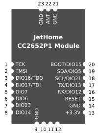
The module is made in the format of a unified JetHome wireless module 28 x 18 mm in size with contacts located along the perimeter of the module. Module pin assignment (top view):
| Module pin | Microcontroller assignment/pin |
|---|---|
| 1 | TCK |
| 2 | TMS |
| 3 | DIO16 (TDO) |
| 4 | DIO17 (TDI) |
| 5 | DIO7 |
| 6 | DIO6 |
| 7 | DIO23 |
| 8 | DIO14 |
| 9 | GND |
| 10 | NC |
| 11 | NC |
| 12 | NC |
| 13 | +3.3V |
| 14 | GND |
| 15 | RESET |
| 16 | DIO12(RX) |
| 17 | DIO13 (TX) |
| 18 | DIO21(SCL) |
| 19 | DIO5 (SDA) |
| 20 | DIO15 (BOOT) |
| 21 | GND |
| 22 | ANTENNA |
| 23 | GND |
- Pins 1,2,3,4 are reserved for connecting a JTAG debugger;
- Pin 20 (DIO_15) is reserved for use as a bootloader backdoor. Entry into the bootloader mode is carried out by a low logic level on this pin;
- Pins 5, 6 (DIO_7, DIO_6), depending on the software, can be used to connect LEDs or for other purposes;
- Pins 16, 17 (DIO_12, DIO_13) - UART interface for firmware and communication with the module;
- Pins 18, 19 (DIO_5, DIO_21) are reserved for connecting peripheral devices via the I2C bus;
- Pins 10, 11, 12 are not used.
Module Software
See documentation for supported firmware: Software for sticks and modules based on TI CC2652P1 chip
Module firmware procedure
The cc2538-bsl utility can be used to flash the module (see Flashing TI CC2538/CC2652 modules and sticks using the cc2538-bsl utility)
Before flashing, the module must be switched to bootloader mode (serial bootloader). To do this, it is necessary to reset the module by holding a low logic level at the DIO15 input of the microcontroller (terminal 20 of the module). The module is switched back to the operating mode when the module is turned on/rebooted at a high logic level at the DIO15 pin (module pin 20).
This is true only for firmware recommended for installation (see the “Module software” section).


