Table of Contents
 This page is not fully translated, yet. Please help completing the translation.
(remove this paragraph once the translation is finished)
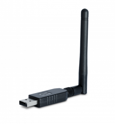
JetHome Zigbee USB Stick JetStick Z2 (CC2652P1)
Description
The JetStick Z2 stick is designed to work as a Zigbee coordinator or router and can be used to control other home infrastructure wireless devices that operate via the Zigbee protocol as part of a Smart Home controller with the appropriate software installed and configured.
The stick is based on a modern Texas Instruments CC2652P1 multi-protocol wireless microcontroller for the 2.4 GHz band (microcontroller description) and features high performance, increased transmitter output power and compact size .
Main technical characteristics:
- 48MHz Arm® Cortex®-M4F processor;
- flash memory 352KB;
- ROM 256KB for library functions;
- SRAM 80KB;
- transmitter output power up to +20 dBm;
- supply voltage 5V from the USB port;
- current consumption in active mode is not more than 100 mA.
Overall dimensions of the stick in the case without an external antenna: 62 x 18 x 10 mm.
The package includes an external 2.4 GHz antenna. The stick can also be used with other external 2.4GHz antennas. To connect an external antenna, use the RP-SMA connector installed on the stick board.
On the board of the stick are also placed:
- button to switch the boot mode of the microcontroller (used to flash the microcontroller). The case must be opened to access the button;
- two LEDs (green and red) that can be used to display stick operation modes. The operation of the LEDs depends on the firmware installed in the microcontroller stick.
The stick is intended for use in residential and office premises. Operating conditions:
- Ambient temperature: 0..+40 С;
- Relative air humidity up to 80% without moisture condensation;
- Closed rooms without aggressive vapors and gases.
The stick comes pre-installed with public firmware or based on it (see p. Supported Firmwares). The manufacturer is not responsible for possible incorrect operation of the stick software.
Attention! This device is not professional equipment for security and control systems. And it cannot be used on objects that potentially pose a danger to the life and health of others.
Hardware Features
The stick is hardware compatible with the original board Texas Instruments LAUNCHXL-CC1352P-2.
The transition to the bootloader mode is carried out at a low logic level at the input DIO_15 of the microcontroller. You can control the state of this input using the “FLASH” button installed on the stick board. A low logic level at the input DIO_15 is set when the button is pressed.
To control an external RF switch, the microcontroller pins DIO_28 and DIO_29 are used.
The LEDs are connected to the microcontroller pins DIO_6 (red LED) and DIO_7 (green LED). A high logic level on these pins lights the corresponding LED.
To connect the microcontroller with a computer, a Silicon Labs CP2102 USB-UART interface converter chip is used.
To control a hardware reset and switch the boot mode of the microcontroller, the DTR and RTS lines of the serial port implemented on the Silicon Labs CP2102 chip are used.
Supported Firmwares
See documentation for supported firmware: Software for sticks and modules based on TI CC2652P1 chip
Stick flashing procedure
You can reflash the stick using the cc2538-bsl utility. See Flashing TI CC2538/CC2652 modules and sticks using the cc2538-bsl utility
Using the stick with Zigbee2MQTT
When using the recommended firmware for the coordinator (see section “Supported firmware”), the stick provides full-fledged work with Zigbee2MQTT. This firmware or firmware based on it is installed by default during the production of the stick and the stick is completely ready to work with Zigbee2MQTT.
See the website for Zigbee2MQTT installation and configuration instructions.
The following parameters must be set in the Zigbee2MQTT configuration file:
serial:
  port: /dev/ttyUSB0

advanced:
  rtscts: false
where:
parameter port: /dev/ttyUSB0 - indicates the file name of the device from the system corresponding to the connected stick. The value of the port parameter may differ from that specified in this example, depending on the operating system used and the number of devices connected to USB;
parameter rtscts: false disables hardware flow control for the given serial port. This parameter can be omitted, but make sure it is not set to true.
